


|
Rockwood Friction Transmission |
|
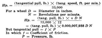
TRACTOR FRICTION TRANSMISSIONS By Charles A Trask, Experimental Engineer for Rockwood The type of friction drive with which this paper chiefly deals consists of two wheels one fiber and the other metal operated by having their rim surfaces pressed together along a line of contact and transmitting a pull due to the resistance of the driven member to sliding or slipping on the driver If we know the pressure and the coefficient of friction in such a drive then the product of the two will give the tangential pull. With any given drive the pull can be resolved into foot pounds per minute and dividing by 33,000 the horsepower transmitted can be determined Thus:
|

|
Copy write 2011, 2012, 2013 not for republication or sale without express written consent. All images are the property of their respective owners and are not to be reused without their express permission. |
|
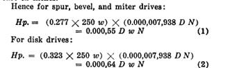
In the most popular combination of friction materials one wheel of cast iron and the other of tarred fiber the following recommendations are made For spur bevel and miter drives where faces have motion of true rolling contact f=0.277. For variable speed disk friction drives where faces do not follow true rolling contact f = 0.324. Also it is recommended that a pressure not to exceed 250 lb be used for each 1 in width of face of fiber. Then P total pressure 250 w when w = width of face in inches. |
|
As the power capable of being transmitted in friction drives varies directly with the pressure it would be ideal to use friction materials with high compression strength. But it has been found that as a fiber material is increased in density to carry greater pressure the coefficient of friction decreases. Therefore as pressure multiplied by coefficient represents pull and as it is impossible to increase the value of one except at the loss of the other no final gain results Pressure withstanding quality of the fiber friction material is therefore the limiting factor in the friction drive If pressure is too high the structure of the fiber gradually yields and breaks down. This breaking down or disintegration at high speeds results in a charring or heating of the fiber it becomes brashy and goes to pieces Everyone knows the result of running on an under inflated or over loaded automobile tire the wall fabric becomes sheared from the rubber heat is generated and soon a new tire is needed The effect of excessive pressure on a fiber friction wheel is very similar It is absolutely necessary that pressures be kept within reasonable limits. The pressure of 250 lb per in of face width of fiber given above represents only about one sixth to one tenth the pressure that would break down the tarred fiber wheel for a short period of running but for average long working periods 250 lb is all that is safe and even that may be high for rim speeds of from 6000 to 10,000 ft per minute.
Application of Pressure
The simplest and best method of applying the pressure between the friction surfaces would be through a foot pedal or a lever that could be drawn up until the pressure is just sufficient to handle the load and then retained by suitable ratchet or awl at any desired position. In every friction drive a greater pressure is required to start a load owing to force required for acceleration and to the fact that the coefficient is less 100 per cent slip than under normal running conditions. Also there will be times when overloads must be carried for a short time as on short heavy grades in sand or when plows are dropped The single pedal or lever permits the operator to readily meet all these conditions just as a hand controlled belt tightener might be desirable to meet short overloads so that the belt is not always operated under highly destructive tension.
Industrial and farm vehicles are frequently placed in the hands of those whose muscular development exceeds their mental development and it is necessary to either train the driver in order to obtain approximately the correct pressure or make the drive foolproof to guard against his lack of mechanical sense. Hence for tractor service it seems advisable to consider the independent application of a fair operating pressure under normal load conditions and then provide auxiliary means to obtain greater pressure for short periods as the operator may find that the conditions warrant. This arrangement can be carried out through a lever or arm controlled by a spring which will always operate the friction members under a fair average pressure when engaged like the ordinary automobile clutch and an auxiliary lever or pedal provided without ratchet or stop to be effective only as long as the operator exerts pressure through them. In any event while sufficient pressure is necessary to operate the friction drive without undue slip practically all the trouble encountered is caused by excessive pressure and some guard must be provided against its continual use. Like the belt drive the ordinary friction drive operates with only a small percentage of slip and any operator soon becomes able to tell if this becomes excessive
Slippage
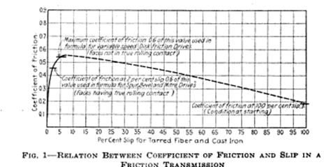
Fig 1 shows a curve representing the typical relation existing between coefficient of friction and the slip between the driving and the driven wheels. This relation is quite similar to that holding true for the ordinary pulley and belt drive Starting at zero per cent slip the coefficient of friction or the resistance to slipping increases and reaches a maximum at about 6 per cent slip. This is the point of maximum pull from then on the coefficient decreases again until at 100 per cent slip it is only about one third that at 6 per cent. The common practice is to design a belt drive for a value of the coefficient corresponding to 2 per cent slip Likewise 2 per cent slip is used in designing friction drives having spur bevel or miter shapes in which the faces follow motions of true rolling contact At 2 per cent slip on the curve the value of the coefficient of friction as shown is about 0.462 However the curve represents values under ideal conditions as obtained in laboratory test To provide a fair factor of safety for average working conditions the actual value is reduced 40 per cent giving as a conservative working value of the coefficient of friction 0.277 as used in the calculations for formula 1. In disk friction variable speed drives it is impossible to design for a fixed percentage of slip between the driving and the driven members as a slight twisting action always occurs on the wheel face owing to the lack of true rolling contact and the actual slip varies with the different positions of the wheel on the disk. The tendency in this arrangement of drive is for the slip to increase until for the different points on the face the total average value corresponds to the value of the coefficient just sufficient to carry the load under the pressure being used. Naturally for greatest transmitting capacity this is represented by the values at the peak of the curve. Therefore it is customary to design disk drives on the basis of average maximum values In the case of the curves shown in Fig 1 a fair average maximum value of the coefficient is 0.50 and 60 per cent of this taken as a fair working value is 0.324 as used in formula 2 Between values of 6 and 100 per cent slip shown by the broken line the relations on the curve are assumed. These no doubt are approximately correct and in any event the values within these points do not materially affect practical operating conditions. The reduced value of the coefficient at 100 per cent slip explains why for a given fixed load a proportionally higher pressure is required at starting and also why this condition is independent of the pull needed to accelerate the load from rest. |
|
Operating Speeds Since power is merely the rate of doing work and any given friction has a fixed maximum tangential pull corresponding to the pressure of contact and the coefficient of friction the power transmitting capacity of friction drives varies directly with the speed of operation. There appears to be no particular limit to the safe operating speeds of friction wheels such drives having been operated at rim speeds up to 13,000 ft per minute but for average conditions the surface speed may be anything up to 6000 or 8000 ft per minute.
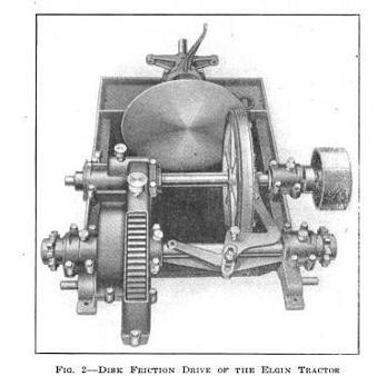
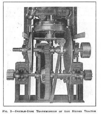
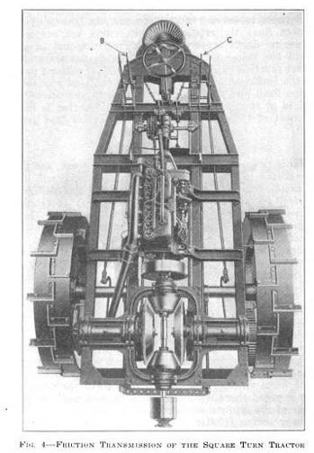
Design and Installation In the case of variable speed disk drives these surface speeds should be obtained by the use of disks of large diameter rather than by high rotating speeds so that in low gear position the friction wheel will reach such a point on the disk that the surface speed will be moderate. For this reason the operator should slow down his engine when starting the load so that when the surfaces are engaged there will be less slip to overcome and less wear of the friction surfaces as a result In mounting friction transmissions the speeds usually being high it is well to see that all parts are properly balanced ball or roller bearings both radial and thrust of the self aligning type or bearings mounted in self aligning housings should be used to compensate for possible springing or deflections of the shafts and for distortions owing to road inequalities. This point is important as otherwise bearing trouble may develop. The average designer appears to consider that his shafts are called upon to transmit only a given torque In friction drives they must also carry the pressure and maintain the correct alignment of the faces of the friction members. Actual operating conditions are not those of the erecting floor design ample bearings and shafts arrange to protect the friction surfaces from dirt and oil make friction members of sufficient size to require only reasonable pressure and then let the user know at least the basic principles of the drive which he is to operate If this is done the drive will be successful and will be just as dependable as any belt chain and sprocket or toothed gear drive If the drive fails to handle its load or wears badly do not blame the transmission when the fault is due to inadequate size or to improper installation. There is a real advantage to the tractor in the extreme simplicity the flexibility the soft velvet clutching action and the high efficiency of the friction transmission. It means longer life of the entire machine greater ease in handling and more work done per gallon of fuel Friction Transmission Types Fig 2 shows a simple form of disk friction drive mounted in a substantial frame as applied to the Elgin tractor. Three pins projecting from the engine flywheel engage the spider that drives the disk shaft The pressure is applied through the lever shown Six forward positions and a reverse are provided thus permitting the engine to work at its best speed regardless of the load. When used for stationary power purposes the pinion on the countershaft is disengaged by pulling the button shown above the left hand bearing Fig 3 illustrates the double disk transmission on the Heider tractor. In this arrangement the fiber friction member is a part of the flywheel both disks are keyed to the countershaft which slides endwise to bring the disks into frictional contact with the fiber being moved to the right to go ahead and to the left to back. To increase speed the engine and with it the fiber friction wheel is moved toward the center of the disks Seven speed positions are provided. This machine has been built for ten years and large numbers are in use The National tractor has a similar transmission arrangement. The transmission in the Port Huron tractor is similar to that in the Heider but instead of moving the engine when changing speeds the friction wheel slides on the rearward extension of the crankshaft In the Square Turn tractor Fig 4 only one speed reduction is provided. The levers B and C operate eccentrics carrying the large bevel friction wheels. The operator can cause both road wheels to go forward or backward or one to go back and one forward at the same time. The machine has a single castor wheel at the narrow end this is the rear end when plowing the plows being underneath. When towing the driver's seat is swung around to the opposite side of the steering wheel the driving wheels then being in the rear No differential is required. The machine weighs 7800 lb has 70 in driving wheels and a 40 hp engine.
THE DISCUSSION George A Weidely MSAE: I noticed that on some of the tractors illustrated the fiber friction member was the driver. On others the fiber friction was driven. Just which is the proper method and why? W D Hamerstadt: Theoretically I do not believe it makes much difference whether the fiber wheel drives or is driven. One practical condition that enters however is the wearing of flat places on the fiber. That can occur only when the fiber wheel is driven. Although such trouble constitutes one of the principal talking points against the friction drive as used in automobiles it does not occur as much as people may think. I have operated friction drive cars very extensively with the fiber driven member and never encountered such trouble.
Service Differs on Tractors and Automobiles In tractor designs where there is a relatively great speed reduction through the friction members the large diameter metal disk used as a driven member seems to work out best I believe however the most important consideration is the nature of the work Tractors operate by far the greater part of the time at low speeds and under the heaviest loads as in plowing. Now the highest efficiency in the variable speed disk friction drive is when the fiber wheel is at the outermost point of the diameter of the disk. Therefore to obtain highest efficiency during the period of greatest work and when most needed as on heaviest pulls I would recommend the fiber as the driving member. The condition is exactly reversed with automobiles most of the service is on high speed with light loads For such service I would recommend the fiber member be the driven member. In either case the load carrying ability of the transmission should be at all times equal to that of the engine.
Slippage and Coefficient of Friction DL Gallup MSAE: What is the reason for the coefficient of friction of spur bevel and miter gear drives being less than for variable speed drives? Mr Hamerstadt: The point has been brought out by Mr Trask Spur miter and bevel drives have a motion of true rolling contact between their faces and like belt drives they are designed for a uniform constant slip of say 2 per cent The value of the coefficient of friction for such drives is therefore that value corresponding to 2 per cent slip on the slip coefficient of friction curve after deducting 40 per cent as a factor of safety for actual working conditions In disk friction drives there is a certain twisting action of the fiber wheel against the face of the disk and for each different position of the fiber wheel on the face this twisting action and the total average slip vary. Taking a case in which the slippage on the fiber is 4 per cent at a point near the center of the face of the disk 3 per cent at a point midway between the center and outer edge of the fiber and 2 per cent at the outer edge each of these points will be pulling with a different value of the coefficient of friction corresponding to its rate of slip on the slip coefficient of friction curve As the load increases there will be a tendency for each point to slip more so as to have a greater pulling capacity. A glance at the slip coefficient of friction curve readily shows that the different points with their varying slippage exert maximum pull only as the slips approach values corresponding to maximum coefficient values at the peak of the curve say 6 per cent slip This average maximum value of the coefficient of friction is used therefore as the basis of design for variable speed friction drives of course after allowing the 40 per cent factor of safety It is not based on a predetermined fixed value of slip as for spur miter and bevel drives Mr Gallup: I supposed that spur bevel and miter drives were more efficient. Mr Hamerstadt: They are more efficient than variable speed drives. However that statement may lead one to underestimate the efficiency of the variable speed drive whereas it is very good. The curve shows that the maximum value of the coefficient of friction is reached at about 6 per cent slip that is the maximum capacity is reached with a slip never exceeding 6 per cent. After that the decreasing values of the coefficient of friction will simply result in stalling the drive. The 6 per cent slippage loss represents practically the entire loss in efficiency except the friction loss in shaft bearings and the slight loss caused by rolling friction of the two surfaces In proper design the shaft bearings should cause little loss and with a dense hard smooth fiber surface the rolling friction seems almost negligible. We might say therefore that with friction surfaces clean and in good operating condition as must hold true for the slip coefficient of friction curve shown the efficiency will never be less than 94 per cent at maximum load and at lower loads it will be even greater I do not believe there is a toothed gear drive that can show continuously as high an efficiency. CS Crawford MSAE: We design toothed gear drives to transmit power as efficiently as that but they are not manufactured that way. Mr Gallup: What is the maximum commercial capacity in horsepower of a friction drive? Mr Trask: I do not think it has ever been reached. Mr Gallup: Two thousand horsepower. Mr Trask: I see no reason why that figure cannot be reached. I do not know what is the largest drive we have turned out but 5 in shaft sizes are not uncommon. The Panama Canal Commission has installed machinery for handling coal at Balboa and Colon where the storage capacity is I believe about 900,000 tons. A number of large bevel friction drives are used for handling this coal most of the shafts as I remember them are about 5 in diameter and they run at fairly high speed I believe the units handle 3000 tons per hour .
Protection of the Friction Members A Member: We have a tractor with a straight faced disk, What provision is made against trouble from sand and grit? Mr Trask: The friction members are not left exposed as shown in the illustrations Generally they are protected just as carefully as toothed gear transmissions. A Member: Is there any difference in the capacity when such a drive is inclosed particularly when grease or oil gets on it? How does lubricant affect it? Mr Trask: Oil and grease must be kept off of the friction surfaces Any mechanism operating close to the friction surfaces can be shielded in some way to prevent throwing lubricant. A Member: Should the surfaces be absolutely dry? Mr Trask: They should be shielded from road splash and rain. However we have found that a very small sprinkling of oil does not cause much harm. Mr Crawford: Are compounds of any kind used occasionally on the disks as for belt drives? Mr Trask: We have experimented with dressings but it has been found that best results obtain from incorporating a small amount of compound in the fiber when it is being made
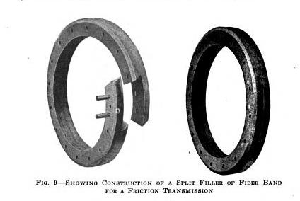
Friction Wheels Operate Better in Damp Weather Mr Hamerstadt: A fiber friction wheel invariably operates better in damp weather It seems to pull more owing to the fact that the material absorbs moisture. Any friction dressing must therefore be hygroscopic in nature. The moisture absorbed seems to toughen the fiber. Rosin or greases should never be used In the presence of heat due to slippage the rosin will melt and then cause slippage. Oil and grease soak into the fiber reduce the coefficient of friction and cause a high rate of slippage After becoming absorbed it is almost impossible to get them out. Mr Crawford: Have devices ever been applied to these tractors for truing the fiber member in case flat spots or anything of that kind should develop. Mr Hamerstadt: That used to be brought up as advisable for automobile friction drives but I never heard of it or the need of it for a tractor I can see no real commercial need for that attachment on the machine. The friction rings are made with a split lap and one of those wheels can be replaced in a half hour.
Comparison with Belt Drive Mr Weidely: This friction drive has been likened to a belt a number of times but I do not see the similarity. A friction drive depends upon certain contact pressure and Mr Trask made the statement that it did not require any considerable area of contact. A tight belt is not required in a belt drive but smooth surfaces and many square inches of belt contact are needed. According to Mr Trask these are not needed in a friction drive Mr Hamerstadt: The belt drive is similar to the Gabriel snubber. An enormous pressure is introduced against a body by taking one or more wraps around it with a cord or band and then pulling on the cord. We all know the effectiveness of the cable drum or winch. Area absolutely is not required in a belt drive to transmit power but we do need the wrapping pressure of the belt against the pulley face just as in the Gabriel snubber .A belt one inch wide will transmit the same power to a pulley as one ten inches wide if they both have the same arc of wrap the same tension and the same speed. A Member: Then why is compound used on a belt? Mr Hamerstadt: A compound or dressing applied to a belt will increase the grip or value of the coefficient of friction between the surfaces Of course if we can increase the value of the coefficient of friction then for a given pull the pressure need not be so great and likewise the tension in the belt that causes the pressure may be less in other words belt dressing will permit a slacker belt as long as its effect lasts. Mr Crawford: The most satisfactory belt drive however is with a slack belt having a large arc of contact on the pulley. Mr Hamerstadt: Yes if the arc of wrap of the belt is great it results in a much greater total pressure of the belt on the pulley and of course the power that can be handled is dependent on this pressure.
Friction Drive Rim Speed A Member: Is there a definite speed at which the friction drive members should operate? Will it give extra efficiency or uinder efficiency or burn itself up by going too fast? Mr Hamerstadt: I know of no particular limit Friction surfaces can and do commonly operate at speeds of 6000 to 7000 ft per min Of course for a given amount of power the higher the rim speed the less the tangential pull and therefore less pressure is required between the friction members. Like the belt drive it is economy to operate at high speeds I have known of frictions to operate at speeds as great as 13,000 ft per min but this seems too high In any case as the speed increases the pressure on the friction surfaces should be reduced as otherwise the flexing or working of the fiber at the high speeds will generate excessive heat and do damage. George T Briggs ASAE: Should there be a definite size depending on the amount of load Are there varying sizes of fiber wheels. Mr Trask: There are no fixed stock sizes of friction wheels. Any size within the limits of mechanical construction can be supplied and by following formulas which I have given any engineer can tell what size to use. A Member: If it is desired with a belt drive to double the power transmitted at a given speed by two members one driving and one driven the width of the belt could be increased. What is done with a friction drive for a similar case Is the pressure or the width of the driving disk increased or what is the limiting factor. Mr Trask: The surrounding conditions govern that If space were available they might be increased in diameter. In a belt drive the diameter of pulley or width of belt can be changed In a friction drive the diameter of friction wheel or its width of face can be increased. Mr Hamerstadt: Let me point out in this connection that to increase the width of belt or the face of the friction members does not in either case in itself result in greater transmitting capacity. Belt widths are increased so that the total section of the belt will be sufficient to stand the tension under which it must operate without too great a stretch in other words to increase the thickness of a belt will have just as much effect as to increase its width. Likewise the face widths of friction members are increased only to give a proper distribution of the total pressure necessary to handle the load. In all cases it should be remembered that it is not safe to apply more than a certain fixed pressure against each one inch width of face and greater total pressures can be safely used only by increasing the face widths. Pressure in friction drives and belt tension in belt drives are really the important limiting conditions of these forms of transmission Use of excessive pressures will invariably result in rapid breaking down and destruction of the fiber.
|
|
The connection between Rockwood Mfg Co of Indianapolis Indiana, founded 1882 and the Heider Tractor Company/Rock Island Plow Co is not particularly well documented. Secondary sources have linked the companies fairly often, but direct evidence is somewhat scarcer. Rockwood was already developing and selling complete friction transmission systems by the time Heider’s were introduced to the tractor market and by 1927 they employed over 400 at their factory. The PTO and other advances caused the company to shut down in 1949, the original machines eventually being used to start up Paper Pulleys Inc in 1979. Most every friction drive tractor in the "Tractor Field Book" is listed as a Rockwood Friction except the GS&M, which is only listed as friction. Charles A Trask, Rockwoods developmental engineer appears in a number of publications talking about friction drive technology and calculations, in which the Heider is referenced as one such arraignment. I have not found the "smoking gun" link per se yet, but some of the Rockwood ads show plates with the same design and styling as the Heiders, so I feel fairly comfortable Rockwood was in fact the supplier to Rock Island. I have found confirmation that the GO/National did use Rockwood. Below is an excellent article and discussion from the SOCIETY OF AUTOMOTIVE ENGINEERS in 1918 that covers theory and use of friction drives. |
|
< Return to List |